Hayward Pool Filter Parts List with Diagram (Cartridge, Sand, DE)
By MIKE DEVID
Is there a part in your Hayward pool filter that’s not working, and you’re not sure what it’s called? Maybe you’re having a tough time finding the names of the parts or you’re thinking of buying some replacements.
Or perhaps you just want to check out a diagram of your Hayward pool filter.
Read this guide article, I have discussed all the above queries related to the Hayward pool filter Parts and Diagrams for the Hayward Cartridge, Sand, and DE filter.
Hayward Pool Filter Parts List with Diagrams
Knowing Hayward pool filter parts and diagrams is essential for regular pool filter maintenance. you can learn how to clean, replace, or troubleshoot specific components, ensuring the filter operates efficiently.
When you need replacement parts for the Hayward pool filter, knowing the specific Hayward pool filter parts List with a diagram ensures that the right components are selected. This helps in avoiding issues related to fitment and performance.
Select your pool filter at the below list. I covered all the popular Hayward Cartridges, Sand, and DE pool filters.
Hayward Cartridge Filter Parts Diagram with Label
Hayward cartridge pool filter problems are not uncommon, and knowing the cartridge parts and their functions enables quick and effective troubleshooting.
You can identify the source of issues, whether it’s a malfunctioning valve or an O-ring, and take appropriate action.
Select your Hayward Cartridge pool filter to know the parts and diagram.
Hayward SwimClear Filters 2020...
Hayward Filter Parts List and Diagram of Model: 2020, 3020, 4020, 5020, 7000, 2025, 3025, 4025, 5025, 7020
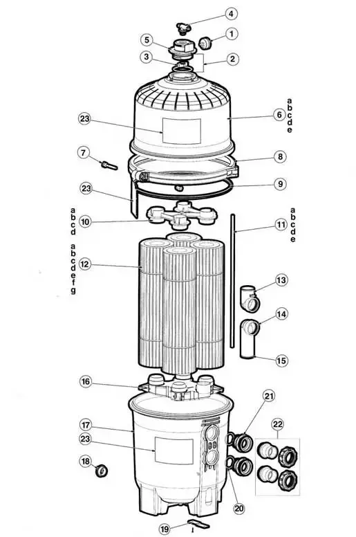
- Pressure Gauge
- O-Ring, Set of Two
- Air Relief Valve Nut
- Manual Air Relief With O-Ring
- Spindle Gear Bushing
- Upper Filter Body
- Clamp Nut and Bolt
- Clamp System
- Metal Reinforced Seal
- Top Manifold
- Air Relief Filter
- Cartridge Elements, 4 Required
- Inlet Elbow
- Outlet Elbow
- O-Ring
- Bottom Collector Manifold
- Lower Filter Body
- 1.5 Inch Drain Plug with O-Ring
- Strap Kit, Optional
- O-Ring
- Bulkhead Fitting
- Plumbing Kit, Includes all 2 -Rrings, 2-Slip Connectors
- Label Pack, Warning Tags, Operations Label Tag, Manual
Hayward SwimClear Filters 2030...
Here is the list of parts diagrams and labels of the Hayward Cartridge pool filter. Hayward 2030, 3030, 4030, 5030, and 7030 Filter.
Hayward SwimClear Filters Parts Diagram
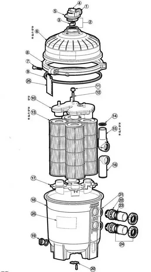
- Pressure Gauge
- O-Ring
- Air Relief Valve Nut
- Manual Air Relief With O-Ring
- Spindle Gear Bushing
- Upper Filter Body
- Clamp Nut and Bolt
- Clamp System
- Metal Reinforced Seal
- Top Manifold
- Air Relief Filter
- Air Relief Tube
- Cartridge Element
- O-Ring
- Outlet Elbow with Pipe
- Bottom Seal Plate
- Bottom Manifold
- Lower Filter Body
- 1.5 Inch Drain Plug with O-Ring
- Strap Kit
- O-Ring
- Bulkhead Fitting
- Union Gasket (2 Pack)
- Union Connector Kit, (Nut, Connector, Gasket)
- Label Pack, Warning Tags, Operations Label Tag, Manual
Hayward Star Clear Filter
Hayward Star-Clear Filters Parts and Diagram of Models C250, C500, C750, C1100
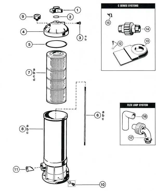
- Locking knob
- O-ring
- Directional vent valve with O-ring
- Filter head (dome) with air relief valve
- Filter head gasket
- Tie rod (250), 18 9/32
- Cartridge element
- Filter body with tie rod assembly
- Pressure gauge, back mount
- Drain plug kit
- Check valve (optional)
Hayward Star Clear - II Filter
Star Clear Cartridge Filter Parts and Diagram of Models c800, c1100, and C1500 Filter
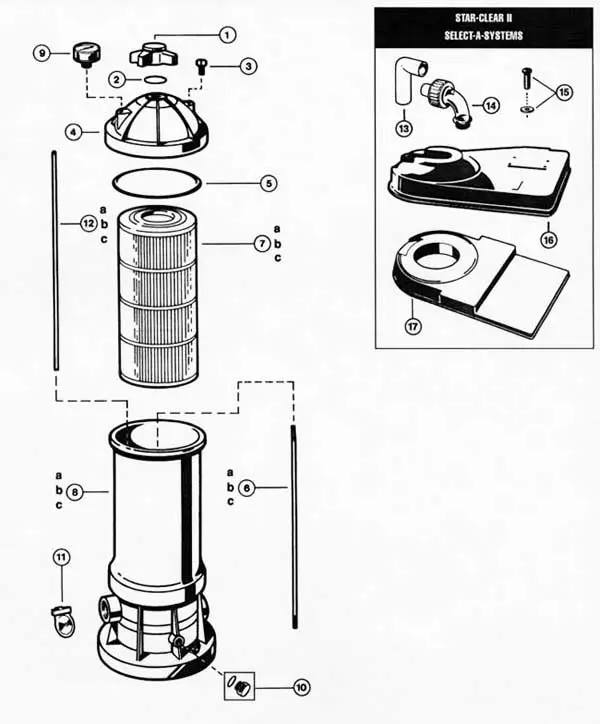
- Locking knob
- O-ring
- Directional vent valve, O-ring
- Filter head air relief valve
- Filter head O-ring
- Tie rod
- Cartridge element
- Filter tank body
- Pressure gauge
- Drain plug kit (plug & O-ring)
- Check valve assembly
- Auto air relief tube
- Flex loop Elbow
- Sweep Elbow Union Assembly
- Pump Mounting Screw w/washer
- Platform Base High
- Platform Base w/Screws
Hayward Star Clear Plus Filter
Hayward C751 Filter Parts, Hayward C900 Filter Parts, C1200 Filter Parts
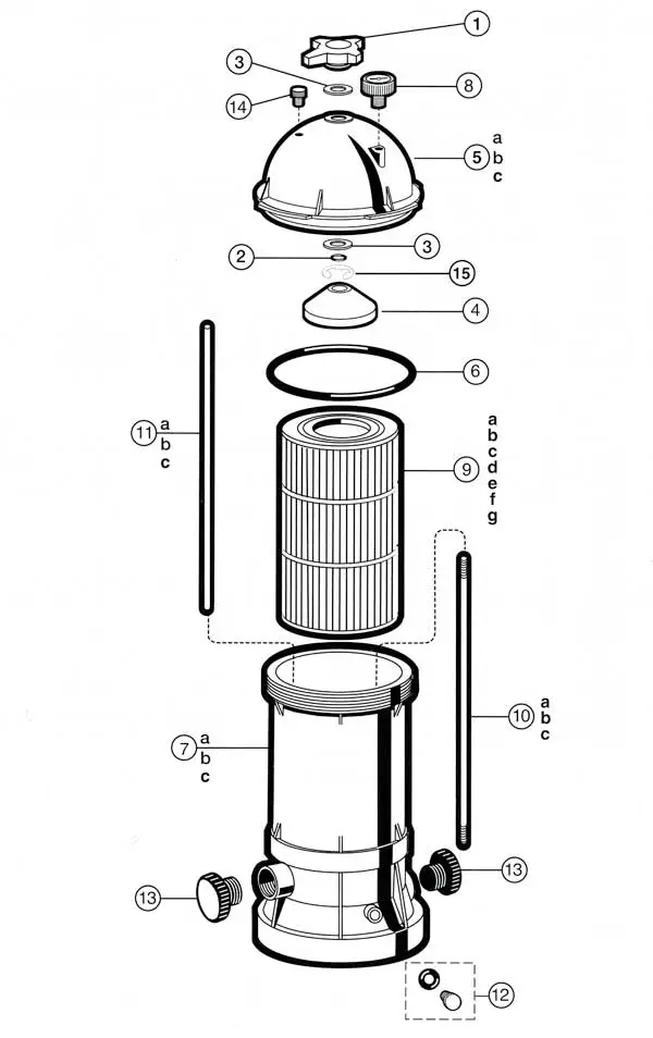
- Locking knob
- O-ring
- Washer (2 required)
- Guide cone
- Filter head, directional vent valve
- Filter head O-ring
- Filter body
- Pressure gauge
- Cartridge element
- Tie rod
- Auto air relief tube
- Drain plug kit (plug & O-ring)
- Check valve
- Directional vent valve, O-ring
- E-Ring
Hayward Sand Filter Parts Diagram with Label
With a knowledge of the Hayward Sand Filter components, you can troubleshoot and carry out minor repairs yourself.
This can save money on service calls and empower you to address common issues, such as leaks or clogs, without professional assistance.
Select your Hayward Sand pool filter to know the parts and diagram.
Hayward S240 Sand Filter
Here is the list of Hayward S240 Sand Filter parts diagrams and labels.
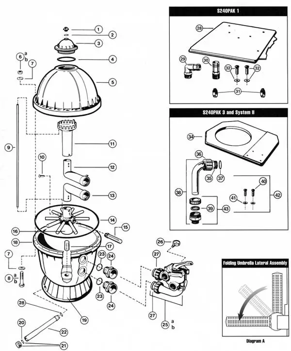
- Manual Air Relief Cap
- O-ring
- Access Cover
- O-ring
- Filter Tank Head (top)
- Hex. Nut w/ Washer
- O.D. Flat Washer
- Hex. Head Bolt
- Plastic Air Tube
- IR Tube Lock Screw
- Top Diffuser
- Internal Diffuser Elbow Pipe (top or bottom)
- Internal Diffuser Elbow Pipe (top or bottom)
- O-Ring
- Lateral
- Lateral Holder Assembly
- Bottom Screen
- Filter Tank (Bottom) with Drain Assembly – Less Skirt
- Filter Support Stand (Skirt)
- Gasket, Included with Drain Cap Kit
- Drain Cap Kit
- Drain Pipe Assembly – Includes Cap and Gasket
- O-ring
- Bulkhead fitting
- Vari-Flo Control Valve Assembly
- Pressure Gauge
- O-Ring
- O-Ring, 1″ O.D.
Hayward S200 Sand Filter
Hayward S200 Sand Filter parts diagrams and labels.
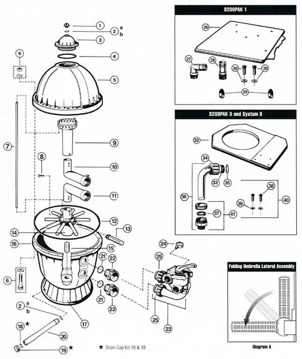
- Manual air relief cap
- O-Ring, 1 3/16″ O.D.
- Access cover
- O-Ring
- Filter tank head (top)
- Head bolt kit (6,7 and 8)
- Plastic air tube
- Air tube lock screw
- Top diffuser
- Internal diffuser elbow pipe – top
- Internal elbow pipe – bottom
- O-Ring
- Lateral
- Lateral holder assembly
- Bottom screen
- Filter tank with drain assembly
- Filter support stand skirt
- Gasket, Replace
- Drain cap kit (20 & 21)
- Drain pipe assembly – cap and gasket
- O-ring
- Bulkhead fitting
- Vari-Flo control valve assembly-1 1/2″
- Pressure Gauge
- O-ring
- Standard Pump Mounting Base
- 1.5 Inch Elbow Hose Adaptor
- 1.5 Inch Strain Hose Adaptor
- Hose Clamp
- Mounting Screw Set with Washers
- .
- Standard Pump and Filter Mounting Base
- Union Ball End
- Union Nut
- O-ring
- Union Elbow With Compression Assembly
- Compression Gasket (1987)
- 1-1/4″ Mounting Screw
- 5/16″ Washer
- 5/16X1-1/4″ Mounting Screws (2) and 5/16″Washer (2)
- Compression Fitting Assembly with Gasket
Hayward ProSeries 244T Filters
Here is the list of Hayward Pro Series S180T, 210T, 220T, 244T, and S270T filter parts diagrams and labels.
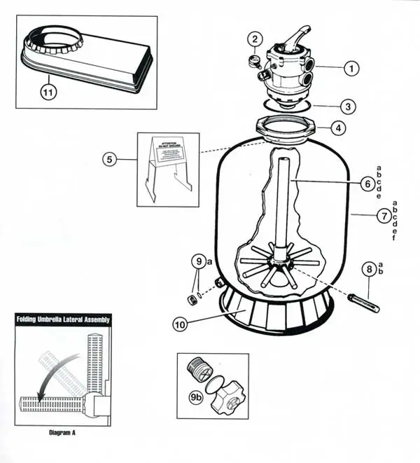
- Vari-Flo XL Control Valve – 1 1/2
- Pressure gauge
- Valve / Tank O-Ring
- Flange Clamp (Dome-Tank)
- Shield- 2004 Corrugated Design
- Folding Umbrella Lateral Assembly
- Filter Tank with Skirt, Drain, and Lateral Assembly
- Lateral
- Gasket
- Drain Cap
- Filter Support Stand Skirt
- System Base
- Swimpure Pool Sanitizing System
- Folding Umbrella Lateral Assembly
Hayward ProSeries 164T Filters
Hayward Pro Series 164T and 166T Sand filter parts diagrams and labels.
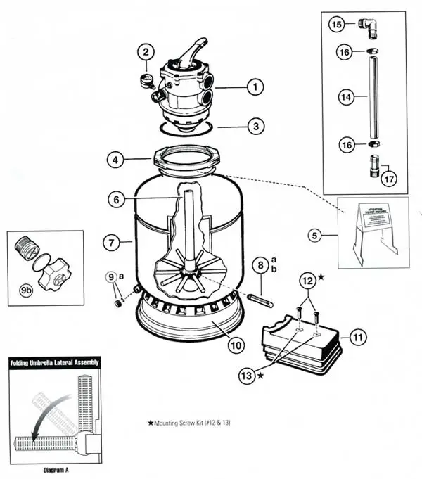
- Vari-Flo XL Control Valve – 1 1/2
- Pressure Gauge
- Valve / Tank O-Ring
- Flange Clamp (Dome-Tank) – Noryl
- Sand Shield – 2004 Corrugated Design (Not Shown)
- Holding Umbrella Lateral Assembly with Center Pipe
- Filter Tank with Skirt, Drain, and Lateral Assembly
- Lateral Assembly
- Drain Cap Kit
- Filter Support Stand Skirt
- Pump Base
- 5/16″ X 3/4″ Mounting Screws (2) and 5/16″ Washers (2)
- 5/16″ X 3/4″ Mounting Screws (2) and 5/16″ Washers (2)
- 22″ Long Hose
- 1-1/2 inch Elbow Hose Adaptor
- Hose Clamp
- 1-1/2 Inch Straight Hose Adaptor
Hayward ProSeries 140T Filters
Hayward Pro Series 140T and 144T Sand filter parts diagrams and labels.
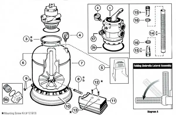
- Vari-Flo XL Control Valve – 1 1/2 (Complete Valve)
- Valve / Tank O-ring
- Flange Clamp
- Pressure Gauge
- Sand Shield
- Folding umbrella Lateral Assembly Center Pipe
- Filter Tank with Skirt, Drain, and Lateral Assembly
- Lateral
- Drain Cap Kit
- Filter Support Stand
- Pump Base
- 5/16″ x 3/4″ Mounting Screw (2) & Washer (2)
- 5/16″ x 3/4″ Mounting Screw (2) & Washer (2)
- 1-1/4 Inch Ribbed Hose
- 1-1/4 Inch / 1-1/2 Inch Combo Hose Adaptor
- Hose Clamp
- Sight Glass
Hayward DE Filter Parts Diagram with Label
Pool enthusiasts and individuals or pool technicians with a general interest in how things work may seek information about Hayward de pool filter parts for educational purposes.
Understanding the mechanics of pool filtration systems can be a fascinating aspect. So, let’s understand Hayward DE pool filter parts with a diagram.
Here is the list of Hayward DE Pool Filters. Select your Hayward DE pool filter to know the parts and diagram.
Hayward Pro Grid DE Filter
Hayward Pro Grid DE Filter parts diagrams and labels.
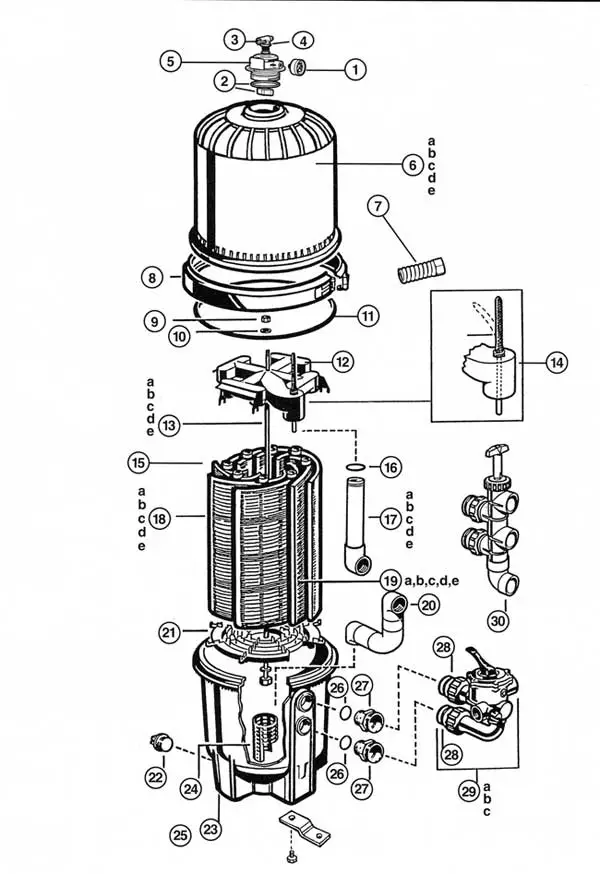
- Pressure Gauge
- O-Ring Kit (2 Set)
- Manual Air Relief Valve Nut
- Manual Air Relief Valve
- Manual Air Relief Assembly
- Filter Head
- Spring, Washer, Brass Sleeve
- Clamp Assembly & Spring Assembly
- Retainer Nut 5/16 inch
- Washer 5/16 inch
- Filter Tank O-Ring
- Top Collector Manifold with Flex Air Relief Assembly
- Retainer Rod
- Flex Air Relief Assembly
- Complete Set of Grids, Collector & Locator
- Outlet Elbow with O-Ring
- Outlet Elbow with O-Ring
- Filter Element (Full Size)
- Filter Element (Short Size)
- Inlet Elbow
- Filter Element Locator
- Inch Plug with O-Ring
- Filter Body
- Element Spacer
- Strap Kit
- Bullhead O-Ring
- Bullhead Fitting
- O-Ring
- Selecta-Flo Assembly (2 Inch SKT)
- Slide Valve Assembly (2 Inch SKT)
Hayward Micro-Clear DE filter
Micro-Clear DE filter, DuraLon, and Permaglass XL Filter parts diagrams and labels.
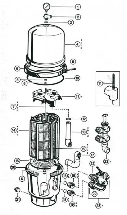
- Pressure gauge
- Relief valve/gauge adapter assembly
- Relief valve assembly O-ring
- Filter head
- Retainer nut 5/16 -18
- Washer, 5/16″
- Retainer rod
- Brass sleeve nut, 5/16″-24
- Clamp assembly w/ spring assemblies
- Filter tank D-ring
- Top collector manifold w/ flex air relief
- Outlet elbow O-ring
- Buttress thread outlet elbow assembly with O-ring & bulkhead fitting
- Filter element
- Filter element (short)
- Filter element locator
- Buttress Thread Inlet Elbow Assembly w/ O-Ring & Bulkhead Fitting
- O-ring
- Bulkhead fitting
- Filter body
- 1 1/2″ Drain plug with O-ring
- O-ring
- Vari-Flo valve assembly- 1 1/2″ NPT
- Clamp spring assembly replacement kit [2 complete assemblies include: (a) washer with a small hole, (b) spring, (c) washer with a large hole, (d) brass sleeve nut]
Hayward Perflex Pool Filter
Hayward Perflex EC-65, EC-75, EC-60, EC-50, EC-50AC, EC-40, EC-40AC, and EC-30 Pool Filter Parts parts diagrams and labels.
Click here to learn about Hayward Perflex pool filter parts. Click Here
Conclusion
In conclusion, understanding Hayward pool filter parts and diagrams is a practical necessity for pool owners, and pool technicians offering benefits such as cost-effective maintenance, troubleshooting capabilities, and optimizing filter performance.
This knowledge empowers you to take DIY projects, make the right product selections, and ensure pool safety.
Please let me know your questions and feedback in the comment sections. Happy Swimming!
